Realisation
Coding
The controller software was developed under the Debian 3.1 operating system with the programming language C. We used the gcc C-Compiler with the avr-gcc extensions for ATMEL mircro processors. For program upload we used the avdfrdude software with a serial cable.
The first step was to develop a small function library which implement easy access to sensors and motors in order to abstract the program logic from the hardware details.
With the help of this library a software tool was developed for the calibration of the connected sensors. The reason was to determine the real minimal and maximal values in the interval of all possible values. The implementation of the control logic gets easier and more concise with it.
The structure of the program is simple: after initialisation of the sensors, the minimal, maximal and current values of each sensor since program start are send to the serial interface. By opposing each sensor to its minimal and maximal stimulus the values for calibration of the robot control program are obtained. The following code extract shows the calibration program.
/* Auszug aus calibration.c */
#define SONIC_NR 4
#define IR_NR 4
#define LDR_NR 4
unsigned int ir_min[IR_NR], ir_max[IR_NR], ldr_min[LDR_NR], ldr_max[LDR_NR];
long sonic_min[SONIC_NR], sonic_max[SONIC_NR];
sonic_t sonic[SONIC_NR];
led_t led;
void init_controller();

int main()
{
 unsigned int i;
 init_controller();
 /* Main loop */
 while (1) {
 printf("IR: ");
 for (i=0; i<IR_NR; i++) {
 const unsigned int val = adc_get(i);
 if (val < ir_min[i]) ir_min[i] = val;
 if (val > ir_max[i]) ir_max[i] = val;
 printf("(%5d, %5d, %5d) ", val, ir_min[i], ir_max[i]);
 }
 printf("\nLDR: ");
 for (i=0; i<LDR_NR; i++) {
 const unsigned int val = adc_get(IR_NR+i);
 if (val < ldr_min[i]) ldr_min[i] = val;
 if (val > ldr_max[i]) ldr_max[i] = val;
 printf("(%5d, %5d, %5d) ", val, ldr_min[i], ldr_max[i]);
 }
 printf("\nSONIC: ");
 for (i=0; i<SONIC_NR; i++) {
 const long val = sonic_get(&sonic[i]);
 if (val != -1) {
	if (val < sonic_min[i]) sonic_min[i] = val;
	if (val > sonic_max[i]) sonic_max[i] = val;
 }
 printf("(%5ld, %5ld, %5ld) ", val, sonic_min[i], sonic_max[i]);
 }
 printf("\n \n");
 led_blink(&led, 1);
 }
 return 0;
}
The following code block shows the simple control logic, like a so-called Braitenberg vehicle. As can be seen, the sensor values are set in relation to each other with simple sums and differences mapped linearly on the speed of the motors.
sonic_t sonic[SONIC_NR];
led_t led;
port_t port_led, port_sonic, port_motor;
motor_t motor[MOTOR_NR];
void init_controller();
void calibrate_sensors();

int main()
{
 init_controller(); /* Initialises hardware */
 calibrate_sensors(); /* Set values from calibration.c */

 while( 1 ) {
 unsigned char c;
 float ir_val[IR_NR], sonic_val[SONIC_NR];
 float ir_impuls[MOTOR_NR], sonic_impuls[MOTOR_NR];
 float ir_diff, sonic_diff;

 /* Read sensor values */
 /* Value of 1 means minimal proximity. */
 for (c=0; c<IR_NR; c++) ir_val[c] = adc_get_norm(c);
 /* Value of 1 means minimal proximity. 1-... */
 for (c=0; c<SONIC_NR; c++) sonic_val[c] = 1 - sonic_get_norm(&sonic[c]);
 /*Infrared red avoids hitting obstacles */
 ir_impuls[0] = -ir_val[1]+ir_val[3];
 ir_impuls[1] = -ir_val[0]+ir_val[2];

 /* Sonic sensors try to reach middle of space around them */
 sonic_impuls[0] = sonic_val[2]-sonic_val[0];
 sonic_impuls[1] = sonic_val[3]-sonic_val[1];

 /* Set the speed finally */
 for (c=0; c<MOTOR_NR;c++) {
 /* Boost sonic value */
 float sum = 10*sonic_impuls[c]+ir_impuls[c];
 if (sum > 1) sum = 1;
 motor_set_speed(&motor[c], sum * MAX_SPEED);
 }
 delay_s(6);
 led_blink(&led, 1);
 }
}
The complete source code for the calibration tool and the control program can be downloaded and used freely.
Electronics
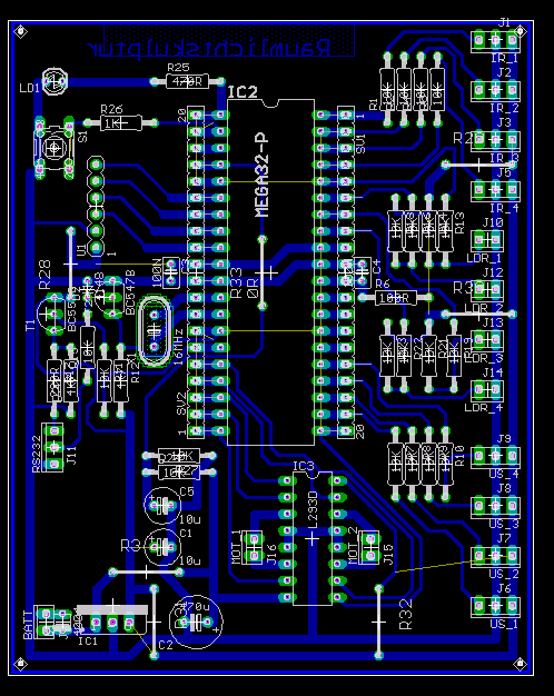 The control of the moveable
room elements is done by a handmade circuit bord on base of
the ATMEL Mega32 micro controller. Next to the controller an h-bridge
for forwards/backwards control and the circuit for serial I/O are the
main components of the layout.
The control of the moveable
room elements is done by a handmade circuit bord on base of
the ATMEL Mega32 micro controller. Next to the controller an h-bridge
for forwards/backwards control and the circuit for serial I/O are the
main components of the layout.
The circuit diagram was designed with the software Eagle. Mit the help of a face tanner the layout was imprinted on a half of an euro platine.
Besides diodes, resistors and stuff the following components are nescessary to realise the control system:
- 1x Atmel Mega32 micro controller, 2KByte RAM, 32 KByte Flash memory, 32 digital I/O ports, 8 analog/digital converter with 10Bit value rang
- 1x H-bridge
- 2x RB 35 motors: reduction 1:600, 10 U/min, Voltage 12V, 6mm gear pole
- 4x SRF05 supersonic distance sensors (Range 4cm-4m)
- 4x Sharp GP2D12 infrarot distance sensors (Range 15cm-80cm)
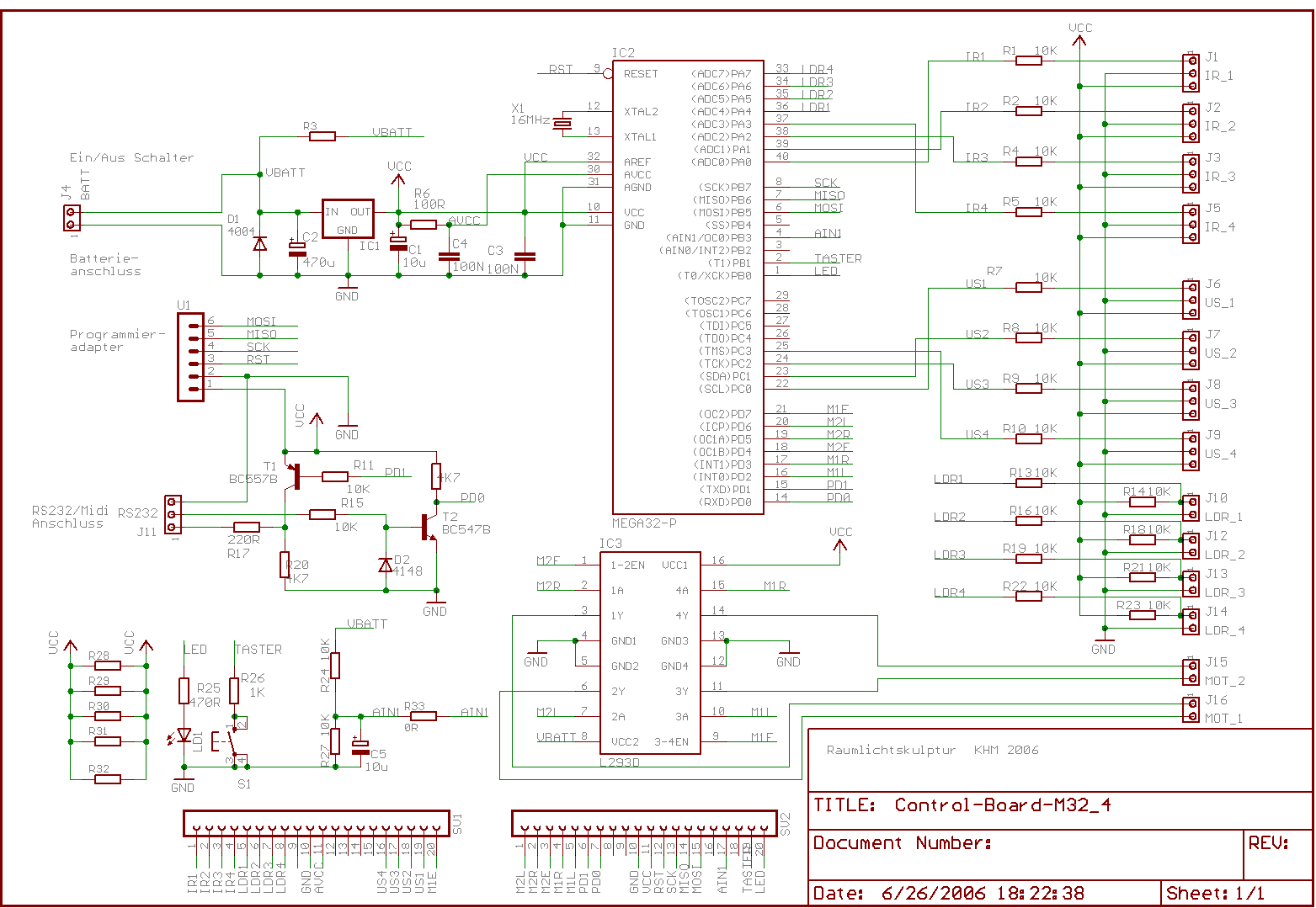 Motors and supersonic
sensors
are accessed over the digital I/O ports. Control of the speed of the
vehicle is achieved through repetitive starting and stopping of the
motors. Through variation of the length of the On and Off intervals the
total speed can be controlled.The supersonic sensors are controlled by
one digital I/O Port. Initially a logical 1 is send to the
port which triggers the emitting of a supersonic pulse. After this the
time is measured until the port changes its value. The time difference
corresponds the distance of an object in front of a sensor.
Motors and supersonic
sensors
are accessed over the digital I/O ports. Control of the speed of the
vehicle is achieved through repetitive starting and stopping of the
motors. Through variation of the length of the On and Off intervals the
total speed can be controlled.The supersonic sensors are controlled by
one digital I/O Port. Initially a logical 1 is send to the
port which triggers the emitting of a supersonic pulse. After this the
time is measured until the port changes its value. The time difference
corresponds the distance of an object in front of a sensor.
Infrared sensors are uncomplicated. They have to be attached to one of the ADC ports of the controller. The ADC send will write the 10 bit value distance values continiously to a register.